Zeven Development
 This is an image title
 This is an image title
 This is an image title
 This is an image title
 This is an image title

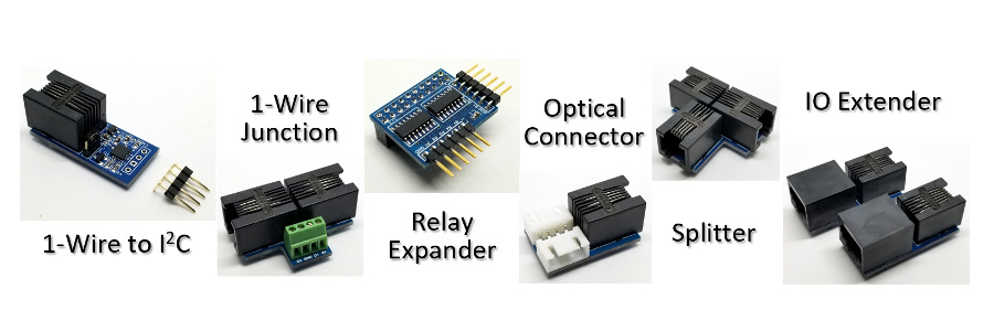
Relay Expander
Expand your IO Expander x4 relay up to 16, x16 relay boards for up to 256 relays.
Using the IO Expander x4 relay interface, daisy chain up to 16 x16 relay boards that are individually controllable. Use the 5V off the first relay board to power your IO Expander as well, but make sure that if you have 5V coming on IN to disable PL3 and disconnect the 12V power in as well.
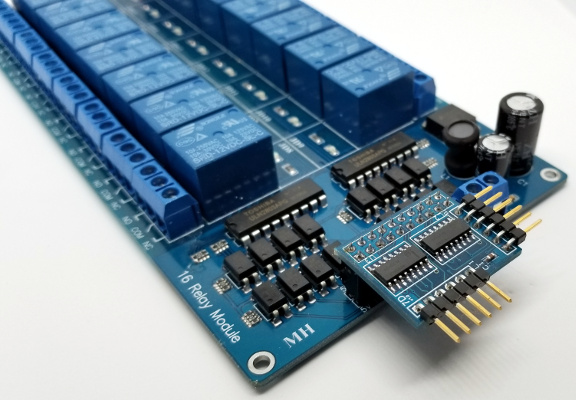
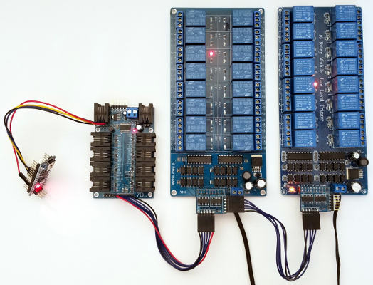
Relay Expander connected to a x16 relay board
Feature List
- Each Relay Expander can control up to x16 low level triggered relays.
- Daisy chain up to 16 Relay Expanders for up to 256 relays.
- Uses 5V from the first Relay Expander to power the IO Expander.
- On power up before initialization all 16 IO lines are in open collector mode.
- After initialization all relays are in the off state.
- 27mm x 22.7mm
| Pin | Function |
|---|---|
| 1 | 5V |
| 2 | R1 |
| 3 | R2 |
| 4 | R3 |
| 5 | R4 |
| 6 | Gnd |
Relay Expander use command 'e'
| subcmd | Function | Mode |
|---|---|---|
| b[#] | Board[1-16] | Dec |
| f | Off | |
| g[n] | Get bits (New v1.14) [Relay #] (New v2.2) |
Hex Dec |
| l[pin] | Latch on pin (New v1.14) | Dec |
| o | On | |
| s(bits) | Set bits | Hex |
Since the same port is used for x4 relay control as well as connecting the relay expanders we need to first configure the IO Expander by letting it know how many Relay [e]xpander [b]oards are connected.
>eb2
2
>
The return is the number of relay expander boards connected. This number is stored in non-volatile storage so you only have to set it one time and it will always remember it, even if the board is powered down or disconnected.
If you specify the incorrect number of boards only the boards at the end will be effected. So if you specify two boards but only have one connected it will still control the first 16 relays. If you have specified one board but have two connected you will not be able to control the last 16 relays.
Let's turn relay [e]xpander [7] and [21] [o]n.
>e7o;e21o
ok
ok
>
Now turn relay [e]xpander [7] and [21] of[f].
>e7f;e21f
ok
ok
>
If we want to set all the relays on/off with a single command, then use the hexadecimal bit equivalent, with the lsb being relay 1. Since the relays are active low, 0 is on and 1 is off.
Let's [s]et relay [e]xpander 7 and 21 on. Binary 1111 1111 1110 1111 1111 1111 1011 1111 is [ffefffbf] in hexadecimal.
>esffefffbf
ok
>
When you set all the relays, the IO Expander will use parallel-output shift registers with latched 3-state outputs to clock all the relay data bits out first to all 256 relays into the shift register, then using a single latch line will set all 256 relays at exactly the same time.
You can also [s]et the relay [e]xpander in a more compact method by using ascii mode. Use the quote character to send out the ascii equivalent instead of the hex string. Don't forget in ascii mode the quote (34), backspace (8), or CR (13) character must be encoded in hexadecimal. Use the SerialWriteRelayExpander() function in the IOExpander library.
>es"....
ok
>
Since you are controlling x16 relays at a time you need to specify at least 4 hexadecimal characters per x16 relay board, but if you only specify 2 hexadecimal characters it will only set the first 8 relays and keep the unspecified previous relay states. Relay states are not persistant between power cycles. The default power on state is all off.
So let's turn off relay 7 and turn relay 3 on. Binary 1111 1011 is [fb] in hexadecimal.
>esfb
ok
>
Relay 3 will now be on, relay 7 will be off, but 21 will still be on.
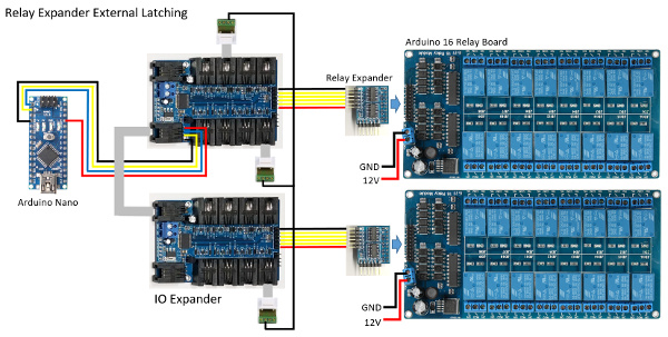
Arduino with an IO Expander controlling two x16 relay boards with Relay Expanders. Notice that there is no 5V wire between the x16 relay boards, but there is one between the x16 relay board and the IO Expander because it is powering it and the Arduino. Since there is no 5V on IN you don't have to remove the PL3 jumper.
External Latching (New v1.14)
The IO Expander now supports external relay latching. This will allow you to first set the new relay states, and then latch or enable the new states using an external GPIO pin. This allows you to use multiple IO Expanders together with multiple Relay Expanders, and using a single GPIO pin turn all the relays on/off at exactly the same time.
Let's use pin 10 connected to pin 4 which already has a pull-up, to enable the latch.
First we have to setup the GPIO pins before we can send the new relay states.
Set the [g]pio pin [4] as an [o]utput with a high [1] level,
on
[g]pio pin [10] we enable the [n]egative edge detection and
finally
we enable the relay [e]xpander external [l]atch on pin [10].
>g4o1;g10n;el10
ok

			ok
10
>
Now we can turn the relay [e]xpanders [o]n/o[f]f/[s]et and then using
the external latch enable it by setting [g]pio pin [4] as an
[o]utput
with a low [0] level for [1] ms. We want pin 4 to return to a high state
so that it will be ready to latch again.
>e1o;e10o;e16o
ok

			ok
ok
>g4o0,1
ok
>
External Latching is extreemly usefull when you need to syncronize multiple relay expanders so that all relays turn on/off at exactly the same time.
					/* IO Expander

 *

 * Relay Expander External Latching

 *

 */


					#include <HardwareSerial9Bit.h>

					#include "IOExpander9Bit.h"

					#include <avr/wdt.h>


					//#define SERIAL_DEBUG

					#define MAX_BOARDS    2


					#ifdef SERIAL_DEBUG

					SoftwareSerial swSerial(8,7);

					#endif


					void setup()

					{

  Serial9Bit.begin(115200,
					SERIAL_9N1);

  Serial9Bit.write(0);                      //
					Set IO Expanders to 9-bit

					#ifdef SERIAL_DEBUG

  swSerial.begin(115200);

  swSerialEcho =
					&swSerial;

					#endif

  wdt_enable(WDTO_8S);


  for (uint8_t
					board =
					1;
					board <= MAX_BOARDS;
					board++)

    SerialCmdDone(board,
					"eb1");


  SerialCmdDone(1,
					"g4o1;g10n;el10");
					// Setup GPIO for external latch
					of relays

  SerialCmdDone(2,
					"g10n;el10");

					}


					void loop()

					{

  static
					uint16_t i =
					0;

  uint8_t r[2];


  r[0]
					= ~(uint8_t)(i
					>>
					8);

  r[1]
					= ~(uint8_t)i++;

  SerialWriteRelayExpander(1,
					r, 2);

  delay(50);

  r[0]
					= ~r[0];
					// Invert all the relays on board
					2

  r[1]
					= ~r[1];

  SerialWriteRelayExpander(2,
					r, 2);

  delay(50);


  SerialCmdDone(1,
					"g4o0,1");
					// Latch all the relays


  wdt_reset();

					}
External Latching Diagram
External Latching in Action
256 Relays (New v1.14)
The IO Expander now fully supports 256 relays per board. Due to cable lengths and capacitance issues the clock and data lines need to be separated to two separate lines each with 8 relay boards. The first 8 relay boards are with R1 and R2 and the next 8 relay boards are with ECHO and TRIG.
256 Relays Diagram
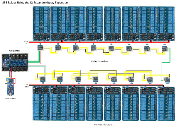
Note: R3 and R4 gets connected to the second lines as shown by the green wires on the far right hand side.
Warning: Do NOT connect the grounds between the lines thus creating a ground loop!
256 Relays in Action
					/* IO Expander

 *

 * 256 Relays

 *

 */


					#include <SoftwareSerial.h>

					#include "IOExpander.h"

					#include <avr/wdt.h>


					//#define SERIAL_DEBUG

					#define MAX_RELAYS    256


					#ifdef SERIAL_DEBUG

					SoftwareSerial swSerial(8,7);

					#endif


					char cmd[10];


					void setup()

					{

  Serial.begin(115200);

					#ifdef SERIAL_DEBUG

  swSerial.begin(115200);

  swSerialEcho =
					&swSerial;

					#endif

  wdt_enable(WDTO_8S);

  sprintf(cmd,
					"eb%d", MAX_RELAYS
					/
					16);

  SerialCmdDone(cmd);

					}


					void loop()

					{

  uint8_t i;

  static
					uint8_t s =
					1;

  static
					uint8_t d =
					0;

  uint8_t r[32];


  for (i
					=
					0;
					i <
					32;
					i++)
					{

    r[i]
					= ~s;

  }


  SerialWriteRelayExpander(r,
					32);

  delay(50);


  if (d)
					{

    if
					(s
					>
					1)
					s >>=
					1;

    else d
					=
					0;

  }

  else {

    if
					(s
					<
					0x80)
					s <<=
					1;

    else d
					=
					1;

  }


  wdt_reset();

					}