Zeven Development
 This is an image title
 This is an image title
 This is an image title
 This is an image title
 This is an image title
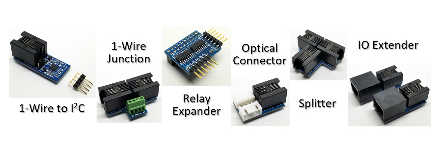
Control Up To 65,280 Relays with your Raspberry Pi!
Use the IO Expander and Relay Expander to control up to 65,280 Relays.
Need to add alot of relays to your project? Then you need the IO Expander with Relay Expanders. Each IO Expander can control up to 16 daisy chained Relay Expanders for a total of 256 relays. Then connecting 255 IO Expanders together you can selectively control up to 65,280 relays.
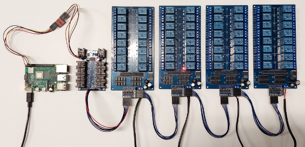
Control Relays with a Single IO Expander.
Feature List
- Use cheap < $15 x16 Relay Boards.
- Easy to use Relay Control Commands.
- Control an Individual Relay or a Bank at a Time.
- No Driver Required. Save Code Space.
- No Data Space to Maintain Relay State.
- No Extra Power Supply Needed.
Parts needed to build a Relay Bank
Wiring Diagram
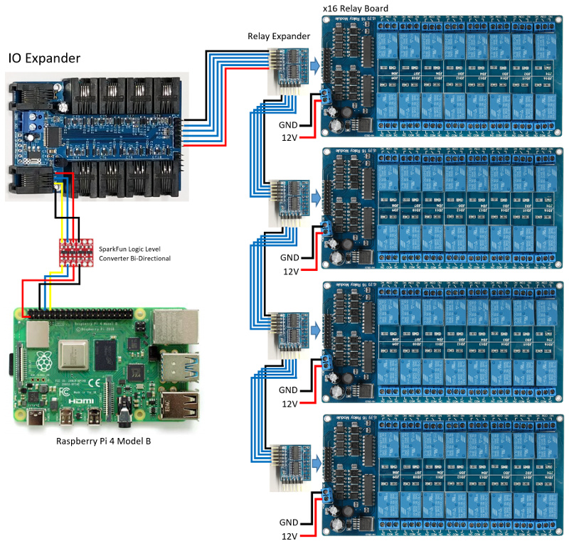
Note: In the above wiring diagram the IO Expander is being powered by the first relay board. All the Relay Expanders are powered from the relay board they are connected to.
#!/usr/bin/env python

import ioexpander

import time


ioexpander.ser.flushInput()

ioexpander.SerialCmdDone(b'eb4')


relay = 1


while 1:

    if ioexpander.TelnetControl(b''):

        continue


    cmd = b'e' + bytes(str(relay),'raw_unicode_escape') + b'f'

    ioexpander.SerialCmdDone(cmd)

    relay += 1

    if relay > 16:

        relay = 1

    cmd = b'e' + bytes(str(relay),'raw_unicode_escape') + b'o'

    ioexpander.SerialCmdDone(cmd)


    time.sleep(0.1)
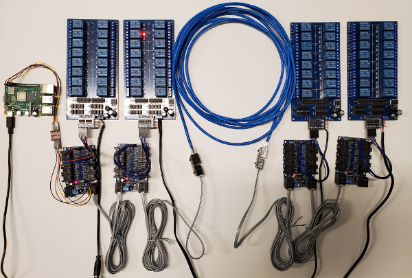
Multiple IO Expanders Controlling Relays
Another way to control relays is to use multiple IO Expanders. This gives us the ability to distribute sensors and relays to a central, or star network, but still interconnect all the IO Expanders on a single serial bus. If you have to separate the IO Expanders up to 4000ft then use the IO Extenders as shown below with the standard blue Cat5 network wire.
Wiring Diagram
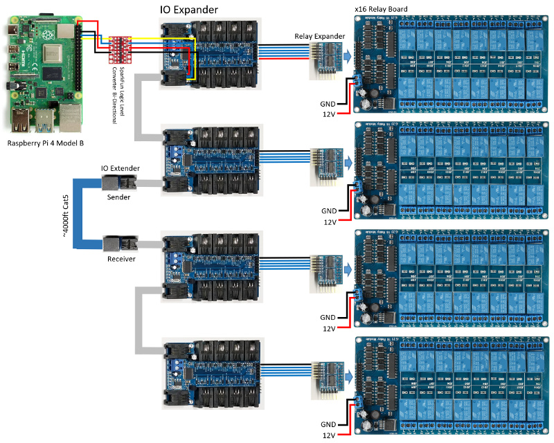
Note: In the above wiring diagram all the IO Expanders are being powered by the first relay board through the serial bus. All the Relay Expanders are powered from the relay board they are connected to.
#!/usr/bin/env python

import ioexpander9bit

import time


MAX_BOARDS = 4


ioexpander9bit.ser.flushInput()


# set IO Expander to 9-bit

ioexpander9bit.ser.write(b'\0')

# switch to simulated 9-bit mode using SPACE and MARK parity

ioexpander9bit.SerialSPACEParity()


for board in range(1, MAX_BOARDS+1):

    ioexpander9bit.SerialCmdDone(board, b'eb1')


board = 1

relay = 1


while 1:

    if ioexpander9bit.TelnetControl(b''):

        continue


    cmd = b'e' + bytes(str(relay),'raw_unicode_escape') + b'f'

    ioexpander9bit.SerialCmdDone(board, cmd)

    relay += 1

    if relay > 16:

        relay = 1

        board += 1

        if board > MAX_BOARDS:

            board = 1

    cmd = b'e' + bytes(str(relay),'raw_unicode_escape') + b'o'

    ioexpander9bit.SerialCmdDone(board, cmd)


    time.sleep(0.1)
Raspberry Pi 9-bit
The Raspberry Pi does not support 9-bit, so we will have to use 8-bit mark and space parity. Only problem is that the Raspbian OS does not support mark and space parity either, so for the Pi4 that uses the BCM2711 (pg.186) we will have to use some undocumented code and use what is called stick parity that is selected by bit 7 (SPS) in the LCRH register.
By default the primary serial port on the header pins 14 and 15 uses UART1 (MiniUART/ttyS0) which does not support any parity bits. We will have to switch the pins to use a different UART0 (ttyAMA0) as the primary serial port instead.
To do this add the following lines to your /boot/config.txt file.
				enable_uart=1

				dtoverlay=disable-bt
Run the following command on your console as well, to disconnect the bluetooth from UART0.
pi@raspberrypi:~ $ sudo systemctl disable hciuart
Python code to set MARK or SPACE parity.
import serial

import termios


ser = serial.Serial(

    port='/dev/serial0',

    baudrate=115200,

    parity=serial.PARITY_NONE,

    stopbits=serial.STOPBITS_ONE,

    bytesize=serial.EIGHTBITS,

    timeout=5

    )


# extra termios flags

CMSPAR = 0x40000000  # Use "stick" (mark/space) parity


# select SPACE parity to clear the address bit

def SerialSPACEParity():

    iflag,oflag,cflag,lflag,ispeed,ospeed,cc = termios.tcgetattr(ser)

    cflag |= termios.PARENB | CMSPAR

    cflag &= ~termios.PARODD

    termios.tcsetattr(ser, termios.TCSANOW, [iflag, oflag, cflag, lflag, ispeed, ospeed, cc])


# select MARK parity to set the address bit

def SerialMARKParity():

    iflag,oflag,cflag,lflag,ispeed,ospeed,cc = termios.tcgetattr(ser)

    cflag |= termios.PARENB | CMSPAR | termios.PARODD

    termios.tcsetattr(ser, termios.TCSANOW, [iflag,oflag,cflag,lflag,ispeed,ospeed,cc])


# select the IO Expander board by setting the 9th or address bit

def SerialWriteBoard(board):

    if board is not None and board > 0:

        SerialMARKParity()

        ser.write(bytes(chr(board),'raw_unicode_escape'))

        SerialSPACEParity()])
So why do I need to control so many relays?
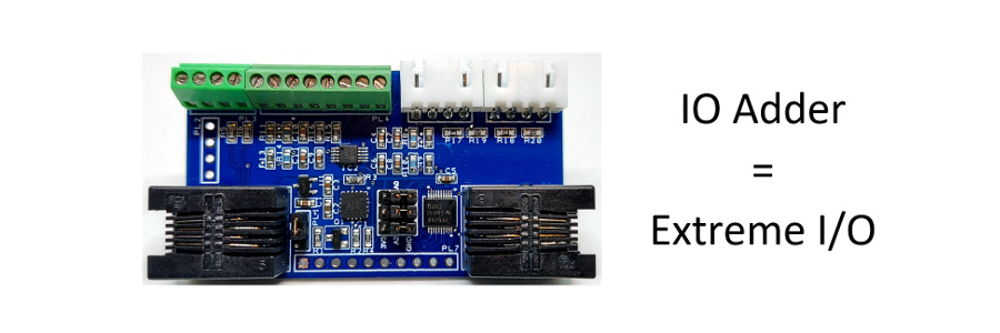
One such application is in Aquaponics or Hydroponics. Lot's of sensors and devices need to be automated down to each grow bed or individual plant. This requires extreme IO and the IO Expander delivers.

So get your IO Expander today and build your system!