Zeven Development
 This is an image title
 This is an image title
 This is an image title
 This is an image title
 This is an image title

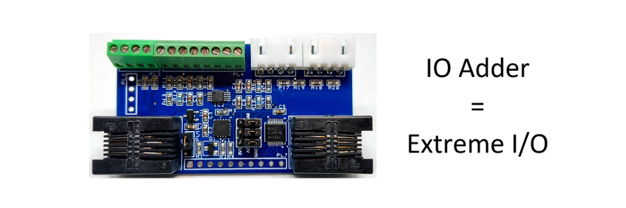
IO Adder
Need to add Additional Remote I/O to your 1-Wire® Bus?
Then you need the IO Adder to give you Extreme IO! See our Hydroponics Growbed Sensors/Display Module Project that makes use of the IO Adder.
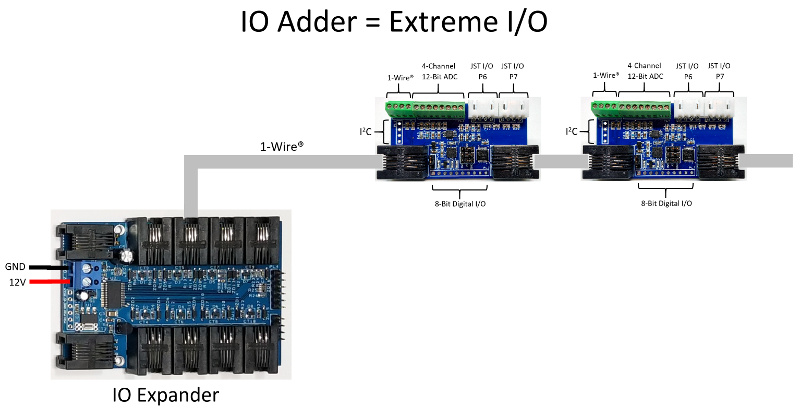
Note: The IO Expander can support up to 16 1-Wire® buses!
Pinout Diagram
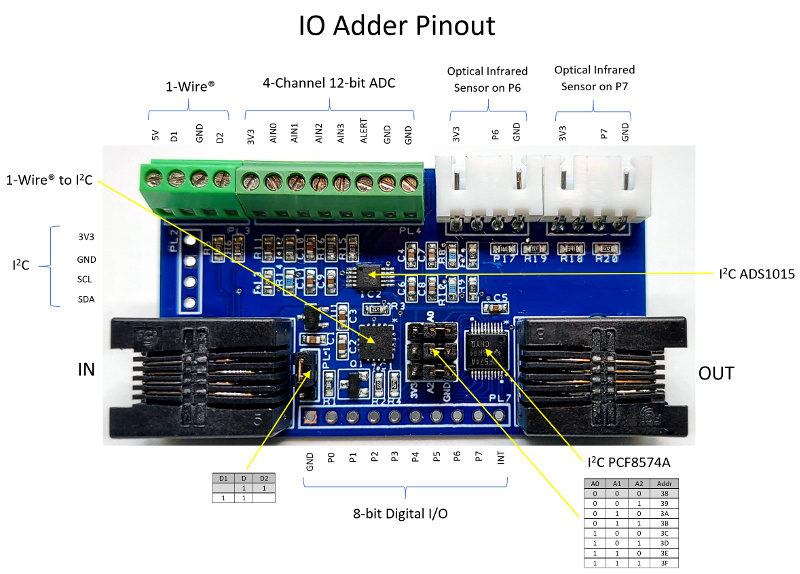
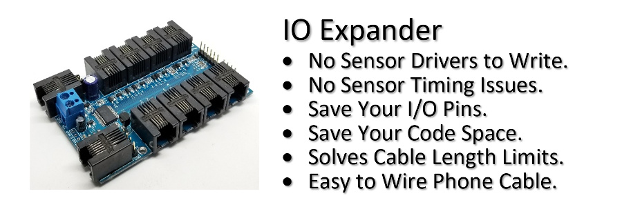
Feature List
- Address Selectable I2C PCF8574A, 8 Digital I/O lines at PL7.
- I2C ADS1015, 4-Channel 12-bit ADC easy connect using screw terminals at PL4.
- ADC supports up to 12V input readings.
- I2C bus connection at PL2.
- 3V3 250mA output.
- 4.7kΩ I2C bus pull-ups on R3 and R4.
- PL1 jumper to select I2C bus on D1 or D2.
- Software selectable I2C bus speeds of 100kHz or 400kHz.
- 1-Wire® Standard or Overdrive(default) speed.
- Easy to connect 1-Wire® sensors using screw terminals at PL3.
- 1-Wire® 100Ω inline resistor drop for distributed impedance matching.
- Supports up to two 1-Wire® buses D1 and D2.
- Easy to connect Optical Infrared Water Level Sensor at PL5 and PL6.
- Optical connection uses 390Ω pull-up and 4.7kΩ pull-down to drive the signal.
- Optical connection uses PCF8574A Digital IO pins P6, and P7.
- Low power 2.6mA typical.
- 59.4mm x 32.9mm
IO Adder Back
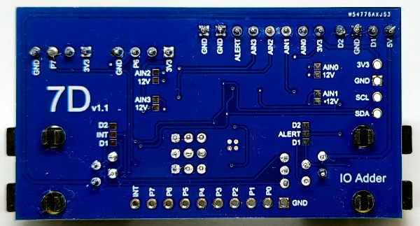
Solder Pad Jumpers
- 12V for AINO
- 12V for AIN1
- 12V for AIN2
- 12V for AIN3
- ALERT to D1/D2
- INT to D1/D2
Note: Only use the 12V solder pad jumper in you are needing to measure greater than 3.3V
Controlling the IO Adder is really easy using the IO Expander.
Using the [i]2c cmd, on pin [4], let's [f]ind all the IO Adders.
>i4f
194319030000001c
19372d03000000c3
>
Let's [s]elect the IO Adder 19431903000[1c] and do an I2C bus sca[n].
>is1c;in
194319030000001c
38
48
>
The I2C scan returned two devices at addresses 38-PCF8574A and 48-ADS1015.
8-Bit Digital I/O
Let's select the [s]ensor [t]ype [1a] PCF8574A using the I2C address at [38]. We have to specify the I2C address here because the default for the PCF8574 is 20.
>st1a38
PCF8574
38
>
Finally let's do a [s]ensor [r]ead.
>sr
3f
>
The read returned bits P7-P0. P7-P6 are low because of the 4.7K pull down for the Optical Infrared Sensors at the JST connectors.
Or you can just read a bit by specifying the bit number after the [s]ensor [r]ead
>sr0
1
>
Returned P0 or bit 0 with a value of 1.
If we want to make P0 an output and set the pin low then we need to do a [s]ensor [w]rite with [fe].
>swfe
ok
>
4-Channel 12-Bit ADC
If we want to use the ADC to read a voltage we can select the [s]ensor [t]ype [1b] ADS1015.
>st1b
ADS1015
48
>
Connecting 3V3 to AIN0, we now do a [s]ensor [r]ead of AIN[0].
>sr0
3.302
>
The ADC returned 3.302V.
If you want to read a higher voltage than 3.3V; up to 12V you will need to enable the resistor divider by soldering the jumper block for AIN0 on the back of the PCB. You can use R1 and R2 in the configuration to do the voltage calculations for you.
To [c]onfigure the sensor set the following configuration values.
>sc2,1200,220
2
1200
220
>
The read returned the FSR of 2 (2.048V), R1=1.2K, and R2=220 ohms. With these values the maximum input voltage would be:
12V * (220 / (1200 + 220) = 1.859V.
Connecting 5V to AIN0, let's again do a [s]ensor [r]ead on AIN[0]
>sr0
5.002
>
The read return 5.002V.
Warning: Inputting a voltage higher than 3.3V directly into the ADC can damage the chip. Always use a resistor divider for higher voltages!
1-Wire is a registered trademark of Maxim Integrated Products, Inc.